Table of Contents
How a Linear Motor Can Help Your Application
Introduction
A linear motor is an electric motor that has been “unrolled”: instead of producing a torque about a shaft, it produces a linear force directly along the direction of motion. No gearbox, no ball screw, no belt, no crank — the moving part is pushed or pulled by magnetic force alone. The result is a drive system with zero backlash, extremely high dynamics and virtually no mechanical wear — which is why linear motors have become the standard solution in machine tools, semiconductor equipment, electronics manufacturing and high-speed industrial robotics.
This page explains how a linear motor works, introduces the two subfamilies used in industrial automation — ironcore and ironless — and helps you decide where a linear motor genuinely adds value to your application, and where it does not.
For the detailed engineering background, continue with the two dedicated pages: How a Tubular Linear Motor Works and How an Ironcore Flat Linear Motor Works.
What a Linear Motor Is
From Rotation to Translation
Take a conventional rotary servo motor and cut it open along the shaft: the stator becomes a flat (or tubular) primary part carrying the three-phase winding, and the rotor becomes a secondary part — a magnet track — that the primary moves along. The magnetic field no longer rotates; it travels along the axis. Where a rotary motor needs a gearbox and a ball screw to convert torque into linear motion, the linear motor produces the linear force at the point of use.
The Lorentz Force
Force generation follows the Lorentz force law:
F = B · I · L · N
where B is the magnetic flux density [T], I the phase current [A], L the effective conductor length [m] and N the number of turns. Because the force is proportional to the current, the servo drive can command force as directly as it commands position — a property with no equivalent in mechanical transmissions.
Synchronous, Permanent-Magnet Operation
Practically every linear motor used in industrial automation is a permanent-magnet synchronous linear motor: the secondary carries high-energy NdFeB magnets arranged with alternating polarity at the pole pitch τ, and the primary carries a three-phase winding (U, V, W) fed with sinusoidal currents, phase-shifted by 120°. A linear encoder reports the position to the servo drive, which computes the commutation angle (field-oriented control, FOC) so that the current vector stays at 90° to the magnet flux — the condition that maximises force per ampere.
Linear *induction* motors — with a passive aluminium secondary and eddy currents — exist and dominate rail-bound transport such as metros and maglev trains, but in industrial automation the synchronous permanent-magnet design is the standard. All NiLAB linear motors are of this type.
The Two Subfamilies: Ironcore and Ironless
All industrial synchronous linear motors share the same physics, but the magnetic circuit differs — and with it the character of the motor. Two subfamilies cover essentially every automation application.
Ironcore Flat Linear Motors
In an ironcore motor the primary carries a slotted, laminated silicon-steel stack. The teeth concentrate the magnetic flux across the air gap, giving the highest force density of all linear motor types — the most force per frame size and per magnet material.
| Strengths | Trade-offs |
| Highest force density; compact cross-section | Normal attraction force between primary and magnet track (several times the rated thrust, present also when switched off) |
| Lowest cost per newton | Cogging (detent force) — minimised by slot/pole geometry and electronic compensation, but inherently present |
| Rugged, epoxy-protected, ideal for machine tables and gantries | Requires a rigid mechanical design and linear guides rated for the attraction force |
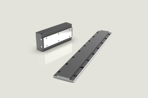
The NiLAB L/LK/L1S ironcore series delivers continuous forces from 150 N to 7500 N and peak forces from 440 N to 15750 N in seven primary frame sizes. Full working principle: How an Ironcore Flat Linear Motor Works.
Ironless Linear Motors (Tubular and Slotless)
In an ironless motor the active coil carries no iron: the three-phase winding is bonded in resin, either as a cylindrical forcer around a magnet rod (the tubular design) or as a flat coil sandwiched between two magnet tracks (U-channel design). With no iron circuit there is no cogging, no normal attraction force and the lowest moving mass — the recipe for the highest dynamics and the smoothest motion.
| Strengths | Trade-offs |
| Zero cogging, zero force ripple | Lower force density — more magnet track for the same force |
| Zero attraction force — no guide-load penalty | Higher magnet cost per unit of force |
| Lightest moving mass: highest accelerations | Tubular: force limited by rod diameter |
| Smoothest motion for optics, metrology, dispensing | U-channel: larger envelope for the same stroke |
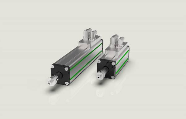
The NiLAB NLi tubular series integrates the complete drive electronics in the forcer, the Green Drive ISO (GDI) packs the same integrated concept into the classic ISO 15552 cylindrical housing, and the NLNS series provides ironless flat motors with moving coils for the highest dynamic requirements. Full working principle: How a Tubular Linear Motor Works.
Side by Side
| Parameter | Ironcore flat | Ironless (tubular/slotless) |
| Continuous force | Highest (up to 7.5 kN per NiLAB frame size) | Moderate |
| Force density / compactness | Highest | Lower |
| Cogging / force ripple | Small, electronically compensated | Zero |
| Normal attraction force | High — must be designed into the machine | None |
| Moving mass and acceleration | Higher mass | Lowest mass, highest acceleration |
| Cost per newton | Lowest | Higher (more magnet material) |
| Typical applications | Machine tables, gantries, presses, heavy pick-and-place | Semiconductor, optics, metrology, dispensing, fast pick-and-place |
Where a Linear Motor Helps Your Application
Speed and Dynamics
With no mechanical transmission, a linear motor is limited only by the magnetic force and the moving mass. Velocities beyond 5 m/s and accelerations of several g are routine — a ball screw reaches its critical speed long before that, and a belt its resonance. If your cycle time is dominated by “accelerate–move–decelerate–settle”, a linear motor shortens every segment of that cycle.
Precision Without Backlash
There is no nut, no gear and no belt to wear or stretch: the mechanical position is the magnetic position, measured by the linear encoder at resolutions down to the sub-micron range. Settling times shrink because there is no elasticity in the transmission — an advantage that shows up directly in surface finish and throughput on machine tools.
Programmable Force
Since thrust is proportional to current (F = B · I · L · N), the drive can regulate force in closed loop: press-fitting, dispensing, forming and testing operations get a freely programmable force profile instead of a mechanical end stop.
Lifetime and Maintenance
A linear motor has no wearing transmission parts: no screw to lubricate, no belt to replace, no gearbox to service. In a machine built for millions of cycles this removes both the maintenance cost and the availability risk of the transmission.
Energy Efficiency
The motor draws current only when force is required; there is no constant-loss transmission chain. Compared with a pneumatic cylinder — which wastes most of its energy in compression and exhaust — an electric direct drive typically cuts the energy per cycle by a large factor. The Pneumatic-to-Electric guide quantifies this with real numbers.
Travel Without Limits — and Multi-Carrier Axes
The magnet track is built from bolted segments, so travel can be extended to many metres. And because the track is passive, several independent forcers can share one track — two, three or more synchronised or independent axes on a single mechanical rail, something a ball-screw axis cannot offer at any price.
Where a Linear Motor Is Not the Best Choice
An honest guide must also state when not to use one:
- Very high force at low speed, short stroke: a ball screw or a hydraulic cylinder is usually cheaper. - Vertical axes: the load must be secured against power loss — a motor alone cannot hold position, exactly as for a vertical rotary axis (a fail-safe brake is required). - Very long, low-duty travels: a rack-and-pinion or belt drive is often more economical when precision requirements are modest. - Extreme contamination (chips, coolants, dust): the epoxy-protected NiLAB designs tolerate harsh environments, but guides, encoders and cable chains need appropriate protection — evaluate case by case. - Simple, fixed end-point motion with no process requirements: a pneumatic cylinder remains the cheapest solution. The P2E guide helps you decide when the switch to electric pays off.
Typical Applications in Industrial Automation
| Industry | Typical linear-motor applications |
| Machine tools | High-speed axes; milling and grinding with critical surface finish |
| Semiconductor & electronics | Wafer handling, SMT pick-and-place, inspection systems |
| Packaging & food | High-cycle pick-and-place, filling, dosing |
| Automotive | Dispensing, screwdriving stations, test benches, assembly presses |
| Pharma & laboratory automation | Liquid handling, high-throughput screening |
| Press & forming | Servo presses, force-controlled joining |
| Laser, waterjet & cutting | XY cutting tables with dynamic contouring |
| Metrology & optics | Air-bearing stages, scanning systems, zero-cogging positioning |
Checklist: Which Technology Fits Your Application?
# **Continuous force above ~1–2 kN?** Start with the **ironcore** series; below that threshold both families compete.
# **Zero cogging or lowest force ripple required** (optics, metrology, smooth dispensing)? → **ironless**.
# **Highest dynamics with the lightest payload?** → **ironless tubular**.
# **Normal attraction force acceptable on your guides?** If not, → **ironless**. See [[en:ironcore_motors:attraction_force|the attraction-force page]] for what it means in practice.
# **Vertical axis?** Either family, plus a **fail-safe brake**.
# **Replacing a pneumatic cylinder?** Work through the [[:en:engineersguide:p2e|P2E guide]] and the sizing calculator.
# **Replacing a competitor's motor?** Use the [[:en:engineersguide:cross_reference|Competitor Cross-Reference Tool]].
How NiLAB Can Help
NiLAB supplies both subfamilies from one source — tubular and ironless motors for dynamics and precision, and the L/LK/L1S ironcore series for the highest force densities — together with integrated-drive versions that combine motor and servo drive in one housing. The Engineer's Guide provides the competitor cross-reference, the pneumatic-to-electric migration guide and the two deep-dive pages on the working principles. For sizing support, thermal questions or custom travels, contact the NILAB technical support: we help you from the first sketch to the running axis.
Summary
A linear motor is the direct-drive answer to linear motion: a travelling magnetic field pushes the moving part with no screw, belt or crank in between. In industrial automation the synchronous permanent-magnet design dominates, in two subfamilies — the ironcore flat motor with the highest force density (paid for with the normal attraction force), and the ironless motor with zero cogging and the lowest moving mass. Choosing between them mostly means choosing between force and economy on one side and dynamics and smoothness on the other — and NiLAB covers both from a single source.